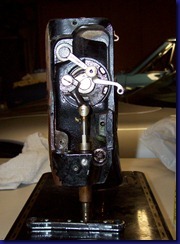
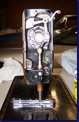
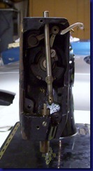
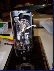
Saturday, July 30, 2011

Busy Beaver

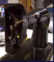
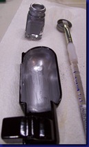
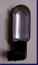
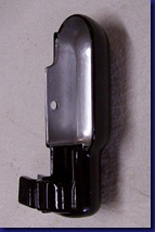
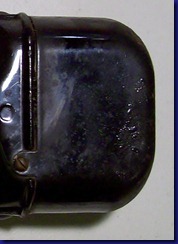
Hello everyone! The last 48 hours have been incredibly productive at my house.  I turned into a Ms. Rusty disassembly animal and as of this evening have her completely torn apart!  There are more than 100 photos to go through and probably 10 posts worth of work to go through and edit, so it may be a few days before my next post. 

In the mean time, I  just couldn’t let another minute go by without sharing the good news of Ms. Rusty’s nakedness (ha ha).  At this very minute she is taking a bath and soaking in Evapo-Rust.

So enjoy the rest of your weekend – I know I will! Laughing out loud

Friday, July 29, 2011

Needle Bar Removal–Part 2

In the last post the needle bar screw, needle bar plug, and presser lever were removed.   This time we’ll remove the actual needle bar – I can tell you can hardly wait! Ha Ha 

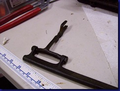
Before removing the needle bar I thought it might be a good idea to take pictures of the position of the various parts as the needle bar goes up and down.  Sounded good but this pesky little fork shaped part kept getting in the way, so I decided to remove it.  Isn’t there an old saying “when in doubt take it out”?

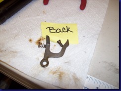
After reviewing the Adjusters Manual, I couldn’t find the official name for the fork shaped part so I’m calling it a “bar fork”.  (Perhaps there isn’t a name for this part in the adjuster’s manual because it isn’t supposed to be removed?)  it was pretty easy to take it out – 1 simple screw.  The first photo below shows the screw location and the second photo shows the part after removal.

fork-lever-screw_thumb     fork-lever-removed_thumb

With that part out of the way, it was much easier to take pictures of the needle bar in the various positions through the stitch cycle.  I’m hoping this will help me put it back together when the time comes.

Needle up, thread take up lever down:      Needle-bar-up-thread-_thumb

Needle down, thread take up lever at mid point:needle-bar-down-thread-take-up-lever[1]

Needle up, thread take up lever up:       needle-bar-up-thread-take-up-lever-u

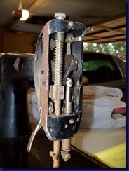
At this point it the time had come to take out the needle bar.  Theoretically it should have come out pretty easily, but as we’ve already learned, theory doesn’t work real well with Ms. Rusty.  So I had to tap out the needle bar (with a wooden dowel) just like the presser bar because it was glued in with rust and gunk.  It also became apparent why there is a hole where the needle bar plug is.  As you can see in this next photo, it wouldn’t be possible to remove the needle bar without this nifty little hole

Needle bar exiting needle bar hole: Needle-bar-removal_thumb

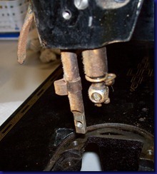
Here’s the front-end of Ms. Rusty without the needle bar:

needle-bar-removed-2_thumbneedle-bar-removed-3_thumb1

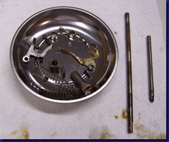
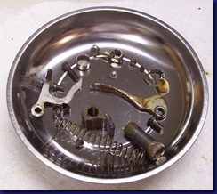
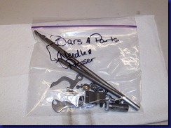
And here are some photos of all the parts that were removed during the presser bar and needle bar removal process.  It may just be me, but after all that work I expected to see a much bigger pile of parts laying there.  By the way, the presser bar is the longer of the two bars.

All-parts-and-bars_thumbAll-parts-removed-2_thumb

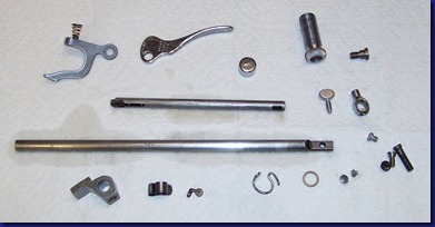
These parts (except for the oil wick) were then soaked in kerosene overnight to removed all the old grease and gunk.  They probably didn’t need to soak quite that long, but it doesn’t hurt them to stay in a bit longer. 

Then the parts were soaked in Evapo-Rust to eliminate any surface rust.  My intention was to soak them for just a few hours, but I forgot about them and they ended up soaking for almost 36 hours!  Not surprisingly, Some of the parts, especially the bars, were blackened with oxidation.  This isn’t unexpected when you leave the parts in too long since this is one of the warnings listed on the label.

black bars

It was fairly easy to remove the black stuff by very lightly sanding the surface of the parts with a fine-grit sand paper.

shiny bars

Then I treated the parts to a spa treatment by lightly rubbing them in sewing machine oil.

clean oiled parts

I then put the oil wick into the thumb screw and applied a liberal amount of oil to the wick.  I pulled it out temporarily after it was partially soaked to show you the difference between dry oil wick and oil filled wick.  The narrow light colored band on the left is the dry portion of the wick.

oil wick partially soaked

Then I placed the parts in a labeled zip lock bag so they are all ready for reassembly in the future.

bagged up

Now what should I tear apart next?  Hmmmm……

Thursday, July 28, 2011

Needle Bar Removal–Part 1

True to my word, today and tomorrow’s segment will be on how I removed the needle bar from Ms. Rusty. Notice I did NOT say this is a tutorial on the correct way to remove the needle bar.  The reason is because I don’t recommend doing things the way I did, but it seemed to work for Ms. Rusty.

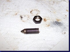
The first step was to removed the needle clamp thumb screw & position screw, which allowed for the removal of the clamp and removed thread guard from the bottom of the needle bar.  Those are all the parts at the bottom of the bar on the right hand side.

bar-attachments_thumb

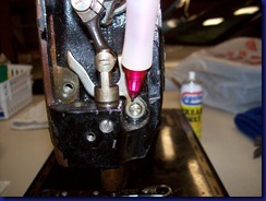
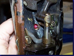
My next step was to remove the screw holding the needle bar in place.  The only way to access it is through a hole on the back side of the arm.  In the photo below I tried (although perhaps failed) to show where this hole is by poking a pink pen through it.

Rear access hole

At this point I needed to move the needle bar to the down position.  Surprisingly, since the presser bar was removed the needle bar moved quite freely. 

Tuesday, July 26, 2011

Presser Bar Removal

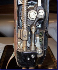
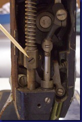
Today, boys and girls, we are going to remove the presser bar from Ms. Rusty.   What is the presser bar you ask?  Well, it’s the steel bar that attached to the presser foot of course!  The presser bar is the tall bar with the spring around it on the left in the photos below.

Front End     Front End close-up

Here we go!  First step is to remove the screw in the presser bar guide bracket

Presser bar guide bracket

Then it’s necessary to remove the presser regulating thumb screw.  Because the name of this part is so confusing, it may help to clarify that the function of this thumb screw is to regulate the pressure that the presser foot applies to the fabric.  (Can you tell I had a hard day at work today?).  The next two photos show the location of the presser regulating thumb screw and what the front end of Ms. Rusty looks like with out this important piece of hardware.

Monday, July 25, 2011

Another lesson learned

With the touch-up paint task behind me, I thought “why not use the silver paint on some of the parts that lost their chrome”.  Sounded good at the time, so I tried it out on a small piece, like the bobbin winder lever.  Here is what it looked like before I attempted to apply the silver paint:
after kerosene (1)_thumb[4]
Putting the paint on made the lever look better, in my opinion. Certainly not back to it’s original condition, but more aesthetically pleasing.
painted silver 2_thumb[3]painted silver_thumb[3]
The next day I decided to check out how the painted piece would hold up to cleaning and oiling that Ms. Rusty would endure after she is back in operation (assuming I can get her there!).  So, I took a cotton swab and dipped one end in kerosene and the other end in oil.  Unfortunately, the paint DID NOT HOLD UP!

Saturday, July 23, 2011

Testing out decals

Today I did a test run of applying decals and experimenting with clear overcoat on the powder coating. 

In a typical restoration, like a featherweight, it is my understanding that you first apply the decals to the painted surface and then apply a clear coat finish over the top of the decals.  The clear coat adds a protective layer over the decals so you don’t have to worry about fabric, zippers, etc. rubbing them off when you are sewing.

However, my restoration is not very typical (as you have probably figured out by now).  I’m planning on powder coating Ms. Rusty and applying decals to the powder coated surface.  The problem is that you cannot apply standard clear coat paint on top of a powder coated surface.  It is just too slick for the clear coat to adhere.  In fact, I’m not entirely sure the decals themselves will even adhere to the surface – which is why I am doing a test run using scrap decals and scrap powder coated metal.

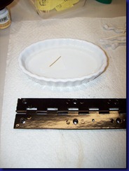
In a previous post I powder coated a scrap hinge to practice my powder coating skills.  I’m using that piece and a single straight line of gold decal for my test.  The first step is to place the decal in some water to help loosen the decal from the background paper (see photo below).

Scrap metal & decal

Friday, July 22, 2011

Touch-up Painting

In this episode I’ll be putting the finishing details on the lamp shade/housing, the tension disk indicator, the stitch length indicator, and the bobbin winder.

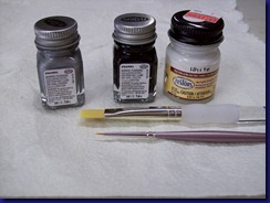
Here is the set of paints and brushes used for this part of the project.  The silver and black paint are enamels and the white paint is acrylic (and it was on sale!).  All three are Testors model paint.

Paint & brushes

Lamp Shade

The inside of the original shade was painted silver, most likely to aid in reflecting the light to the work surface.  Since I had previously powder coated this piece entirely black, it was necessary to paint the inside the shade with silver to restore it to it’s original condition.  One coat wasn’t enough as the black showed through some streaks, but 2 coats did the trick.

One coat:  one coat silver 2 coats:  2 coats silver2 coats silver (2)

Tension disk indicator

Thursday, July 21, 2011

Motor Cover

After I completed all my bead blasting and powder coating this past weekend, I then remembered my poor rusty motor cover.   Luckily, it didn’t take much to set things up again, but it was annoying that I didn’t remember it before now.
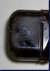
Here are a few photos of the motor cover fresh off of Ms. Rusty.
Motor removed - frontMotor removed - back
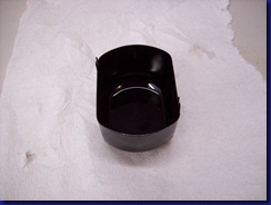
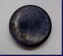
I soaked the cover in Evapo-rust overnight to get rid of as much surface rust as possible. I then took a stiff bristled brush to it to remove all the loose paint on the surface.  Surprisingly, the Evapo-rust removed quite a bit of the paint from the outside but left the inside surface completely intact.  I have been a bit concerned that the Evapo-rust was eating away at some of the paint, but this piece showed me it is just eliminating the rust that the paint was stuck to.  If there is no rust, the paint is unaffected.
inside motor cover after evapo-rustMotor cover after evapo-rust
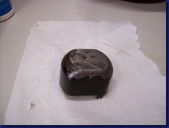
Because the inside of the motor cover is in such good shape, I bead blasted only the outer surface.  The piece was then put through the powder coating process and here is the result.

Tuesday, July 19, 2011

Powder Coating–Part 2

In the last post I covered the equipment and set-up for powder coating so I’ll jump right into the powder coating itself!
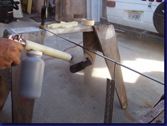
The gun is connected to electricity and to an air compressor.  First one has to push the electrical button, and while holding it down, pull the trigger on the powder coating gun.  The air compressor feeds the powder out of the gun in a soft cloud or “dry mist”.  Through the magic of electricity, the charged powder is electrostatically drawn to the charged metal parts.  As a result, the powder sticks to the part and the excess falls harmlessly to the ground.
The photo below shows my husband demonstrating proper powder coating technique by coating the lamp cover. The close-up shows the texture of the powder “stuck” to the lamp shade.
coating lamp shadedetail & texture

Monday, July 18, 2011

Powder Coating–Part 1

My last post covered the bead blasting portion of the powder coating preparation process.  This post covers the rest of the prep and set-up for powder coating.
Excerpts from Wikipedia: 
Powder coating is a type of coating that is applied as a free-flowing, dry powder… The coating is typically applied electrostatically and is then cured under heat to allow it to flow and form a "skin". … It is usually used to create a hard finish that is tougher than conventional paint. Powder coating is mainly used for coating of metals...
The reasons I’m choosing powder coating vs. painting is because powder coating provides a tougher finish than paint, is less likely to run, and (in my opinion) looks more like the original Japanned finish.  The big down-side is that powder coating requires special equipment.  Since my dear husband has a powder coating set-up I really don’t really see a down-side at this point.(Disclaimer:  if you ask me when the project is done I may have a different opinion – we’ll see!)
Anyway, one key to powder coating is to make sure the parts are clean and have a properly prepared finish.  Then you need to hang them from a metal bar using metal hooks so that electricity can conduct through the metal parts. 
parts ready for powder coatinggear cover - powder coat ready

Sunday, July 17, 2011

Bead Blasting

This weekend I decided to wrap up some loose ends on pieces that needed finishing.  This gave the wonderful opportunity to learn how to bead blast (aka sand blast) and powder coat!  My husband’s hobby is building airplanes, so he happens to have all the equipment I need right in his shop.  If you don’t have such a convenience, then you can either contract it out at a local body shop purchase the equipment yourself.  I don’t recommend purchasing the equipment if you are only going to use it once, but if you plan on using it on a frequent basis then it may be something to consider.  If there are enough questions about it, I could do a post on what equipment I used and how to purchase it.  However, for now the focus will be on the process rather than the equipment.

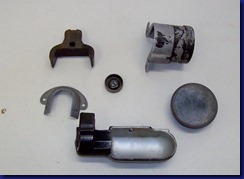
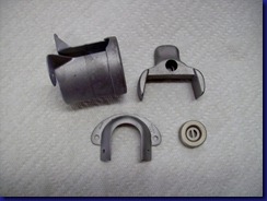
Here are the parts I wanted to strip and refinish (clockwise from upper left):  terminal bracket, rear and front gear covers, lamp shade/housing, bevel gear front cover, and tension indicator.

view 1 Before blasting - 1 view 2Before blasting - 2

Each of these pieces have been previously soaked in kerosene to remove any grease, and then soaked in Evapo-rust to remove any surface rust, and brushed down to remove any loose paint.  Some of the pieces look like they are in pretty good shape, so you may wonder why the bead blasting is necessary.  The primary reason for it is to make sure the surface is smooth, yet textured enough, to promote adhesion of the powder coat.

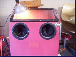
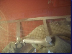
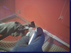
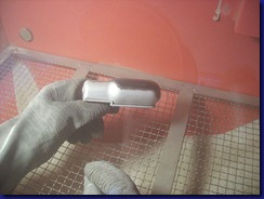
Here is a photo of me bead blasting the other parts in the blasting booth.  The parts go into the booth from a side door.  Then after it is sealed shut, my hands go into gloves from the outside, so the person doing the blasting is completely protected. There is a window in the top to see what you are doing.

100_0546bead blasting

Here is what the front gear cover looks like before and after bead blasting:

Before Gear cover - before blasting  After  gear cover - after blasting - outside

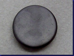
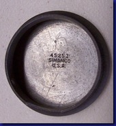
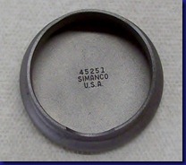
Surprisingly, it only takes off a very thin surface layer and doesn’t have any negative impact on details like engraved SIMANCO part numbers.

Before Gear cover - before blasting - inside  After  gear cover - after blasting - inside

To better demonstrate this, I’ve posted a video on YouTube showing my husband bead blasting the lamp shade.  Here are a few photos for those who prefer pictures to video – see how just the layer of paint is removed from the surface?

lamp cover blastinglamp cover blasted

Here are the parts after blasting. I was careful to not touch them with my bare hand to ensure no trace oil was left on the surface which can mar the powder coat (or paint if you choose to go that route).  Aren’t they pretty!

after blasting - 1

Next time – Powder coating!

Sunday, July 10, 2011

Feed Rock Shafts

First let me start by saying I learned a LOT taking these two shafts out. I learned 1) that the names of these two bars/shafts are so similar that I was getting them confused, 2) how NOT to take out the shafts, and 3) its much easier to take out the second shaft after learning 1 and 2!

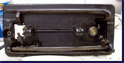
Here is a picture of what I started with:under machine without drive
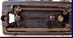
Lesson #1:  The top shaft is called the Feed Lifting Rock Shaft and the bottom shaft is called the Feed Rock Shaft.  From this point forward I’m going to abbreviate them FLRS and FRS, or Top Bar and Bottom Bar, because that’s what I ended up calling them in my head to keep them straight because it took me way too long looking at the Adjuster’s Manual for me to figure out that they even had different names.  For a while I was calling them both “rocker bars” and then thoughts of ‘80’s Big Hair bands flashed through my head, and then……well, I digress.  In the end I disregarded what the Adjuster’s Manual said and just dove in because I was getting too confused.

I first I took LOTS of pictures, because I’m sure I’ll forget something along the way and putting it back together might be a bear.  However, I won’t bore you with the 20+ photos I took from every angle and I’ll just show you the pertinent ones along the way.

My first goal was taking off the feed lifting crank from the FLRS, or top bar.  A front and rear picture of this gizmo is shown below.
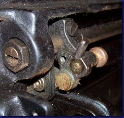
Front end, top feed barFront end top feed bar

I began by removing the ‘feed lifting rock shaft crank clamping screw’ and then attempted to loosen the lifting crank thumbscrew, but it wouldn’t budge.  After trying several other screws in the area, and discovering they were all locked up due to rust or old grease, I sprayed Break Away on each and every joint and screw under the machine.  I suppose one could also use WD-40 or something similar, but this happens to be what I had on hand.
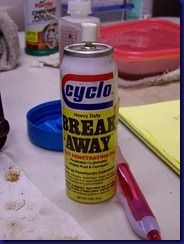
Cyclo break away

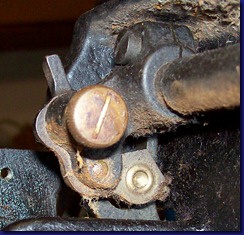
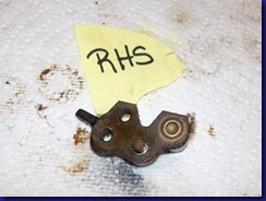
After several applications over a period of a few hours I finally was able to loosen the thumb screw.  Then I removed the screw on the feed lifting crank itself and with a little wiggling took off the crank assembly (see below).  For clarity, I the tag LHS means the side that can be seen when looking at the machine from the front end, or left side of machine.  RHS means view from right hand side, or balance wheel side of machine.
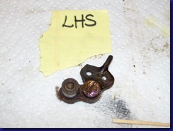
LHS of feed lifting crankRHS of feed lifting crank

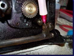
Then came the real fun – remove the FLRS or top bar.  I started by removing the center end screws/nuts from both the front and rear of the top bar.  Here is a picture before the disassembly process showing the center screw/nut on the top and the connecting rod screw below it. 
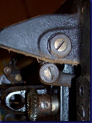
rear end view of machine bottom

At this point the top bar is attached to the machine only by the connecting rod.  This means the rod is flopping around attached only by one screw.  That doesn’t allow one much leverage to remove that dang connecting rod screw, which doesn’t budge for me (of course). 

After busting a knuckle open trying alternatives, I figured out the only way to get any leverage is to reconnect the bar using the center screws.  After reattaching the screws, it was fairly easy to remove the connecting rod screw (big surprise).  Then I had to removed the center screws, again, and then the bar was free!

Lesson #2:  Remove the connecting rod screw FIRST and the center screw/nuts SECOND.
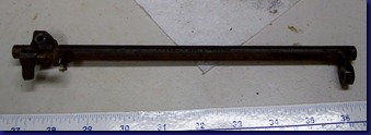
feed lifting rock shaft

After the top bar was removed, I could slide off the thumb screw part of the feed lifting crank.
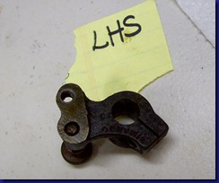
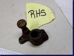
LHS Thumb screw clamp RHS Thumb screw clamp

Here is picture under Ms. Rusty without her top bar, or FLRS, or whatever you want to call it Smile

under Ms Rusty without upper bar

Lesson #3:  It took me 2 evenings, or several hours to remove, the top bar, but less than 10 minutes to remove the bottom bar (feed rock shaft).

I started by removed the screw and nut from the feed forked connection rod
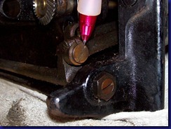
eccentric hinge screweccentric hinge nut

Then I removed the center feed screw/nut.  Here is a photo of just the rear center nut removed and both the screw and nut after removal.
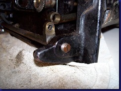
center screwcenter screw and nut

Amazingly the bottom bar just fell out after taking out the front center screw.
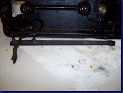
feed rock shaft removalfeed rock shaft with forked thingy

While it was frustrating, and I got one skinned knuckle in the process, I learned a lot taking out the feed bars.  I imagine the next steps, taking out the gears and cranks in the head, will be just as much fun.  Stay tuned!